
Raspberry PI Prototyping board [120483]
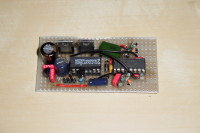
The RPi Prototyping Board is a simple board, designed to break-out the expansion signals from the Raspberry Pi board and provide additional power for any circuit built in the prototyping area.
The RPi Prototyping Board is a simple board, designed to break-out the expansion signals from the Raspberry Pi board and provide additional power for any circuit built in the prototyping area.
The first thing the RPi Prototype board provides is an additional 3.3V DC power supply source. The 3.3V from the RPI expansion header can only provide a small current at around 50mA, so if you want to build any circuits which need more than 50mA, an additional 3.3V power source will be required.
On the RPi Prototyping Board, this is provided by a LM1117 linear 3.3V regulator. This can be either powered from an external or internal DC power source, with the selection made on jumper on J1. The LM1117 can provide up to 800mA if needed with an appropriate heatsink.
If jumper JP1 is set to “internal” then the LDO will be powered from the 5V directly from the Raspberry Pi board.
If JP1 is set to “external”, external power is delivered by a 9 to 12V DC mains adapter through a standard 2.1mm Jack Plug (centre pin positive, outer sleeve 0V) through diode D1. Jumper JP2 will need to be set to “regulator” position.
The second thing the RPi Prototyping board provides is an easy means to access the signals from the Raspberry Pi expansion header connector. A second connector K2, breaks the Raspberry Pi signals out, allowing the user designed circuit to easily connect to them.
Note that there are some signals on the breakout connector are called DNCx (Do Not Connect). As the names suggest these should be not connected, but they may be used on future versions of the Raspberry Pie!
Discussion (1 comment)