
WiFi for MCUs using ESP8266
Feb. 2016: Advice for using the source of the ESP-client.Next minor step developed in Dez. 2015: Version 3.0: Adaptation for newer AT-commands.Next step developed in Jan. 2015: Version 2.0 with additional ESP-clients and support of sliders:
Feb. 2016: Advice for using the source of the ESP-client.
Next minor step developed in Dez. 2015: Version 3.0: Adaptation for newer AT-commands.
Next step developed in Jan. 2015: Version 2.0 with additional ESP-clients and support of sliders:
- New ESP client for Android tablet
- New ESP client for iPhone
- Extended ESP client for PC
- Update of ESP firmware to version 0020000903
- Host firmware V2.0 with support of buttons and sliders
--------------------------------------------------------------------------------
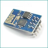
The ESP8266 is a SOC, developed by Expressif, for the extension of your developments with a WiFi communication. Because it has an integrated MCU (enhanced version of Tensilica’s L106 Diamond series 32-bit processor), it can be used as standalone system or as a WiFi frontend for your Arduino, PIC or STM boards. Little breakout boards, named ESP-01 to ESP-12 are rather cheap (around 3.50 $), so many makers like it. These boards differ in number of GPIO-Pins, antenna, etc. Here the ESP-01 is used, which only provides beside RX/TX two GPIO-Ports (GPIO-0, GPIO-2). So it is rather limited for a standalone usage, but a good choice as frontend.
Such a WiFi frontend for a STM32F103 MCU is introduced in the following. It connects the MCU with the WLAN, starts an access point and TCP server and listens on port 3333 for incoming commands. These commands can be issued by any terminal program like Teraterm or PuTTY or more comfortable by a dedicated ESP-Client. The communication between the MCU and ESP8266 runs over the RX/TX lines with 115200 baud.
Test platform
The test platform of the author is equipped with a little STM32 board, running the MCU with a clock of 72 Mhz and offers a rich set of peripherals. The ESP-01 is attached via a connector with 8 pins. As indicators the board has two LEDs, the green one shows the connection status, the red one is controlled over WiFi.
Green LED:
- Off = no connection to the WLAN
- Blink = connection to WLAN, but no client
- ON = Client is connected
Red LED:
- Command Lof = LED off
- Command Lon = LED on
- Command Lbl = LED blink
- Command Lzz = LED blizz
In real projects, these and other commands can be used to control the specific tasks of the development. For test purposes, the board has additional connectors for a 4*20 LCD and a logic analyzer.
An overview schematic and a photo of the test platform have been attached.
Host firmware
The firmware is written in C and as IDE the cost free CooCox has been used. Because the firmware should be integrated in more complex systems, the software architecture is based on a cooperative state machine. In this example, only two threads are used, one for controlling the ESP and one for switching the LEDs. In order to have a definitive status of the ESP after power on, a hard reset will be done first. Then the ESP will be initialized, connected with the WLAN and then it listens for commands. Every two seconds, it sends a message (counting number) to the client as alive signal. The IP address given to the ESP and the address of the connected client are displayed on the LCD. If a Lof, Lon, Lbl, Lzz command comes in from the client, the red LED will be switched appropriately.
The complete CooCox project is attached.
ESP-Client
For a more comfortable command input and better test capabilities, the author has enhanced a TCP/UDP test program. Four buttons for the control of the red LED are added, but other communication is possible as well. This program has been developed with Lazarus, the cost free successor of Delphi. For the TCP/UDP communication, the Inet component has been integrated in Lazarus. This element allows a communication as client or server, IPv4 or IPv6, with and without SSL. For operation with the test platform choose TCP/IPv4, Port 3333, the IP address of ESP given from the router, no SSL. With “connect” a link will be established, “disconnect” terminates the link. With the four LED-xx buttons, commands will be send to the ESP. The “host” button is not used in this application, it starts a TCP-server on the PC. It seems to be a good idea, to store the preferences in an ini-file, may be will be done in the next release. A screenshot of the ESP-Client and an Exe-version has been attached. Store the files named cert and pkey in the same folder than the exe-file.
Experience
The solution works stable and the operation range of the ESP is quite good. The Fritz-Box of the author is installed in his cellar, but the ESP works well in the whole house with a first and second floor. It is better than two tablets of the author. Because the ESP8266 is a rather young product and the developers are very active in order to improve the firmware, it is not yet error free (which software is it ???). And the documentation is improving as well. New firmware releases and enhanced SDKs are coming in rather short cycles.
Nevertheless, the ESP8266 is a fine product for the improvement of your developments.
ESP8266 spec sheet added
Developments in Jan. 2015 Version 2.0
ESP-client for Android-tablet
A rather easy way to create TCP-clients is NETIO. It is cloud-based, meaning you can design and create the client on a PC, upload the result in the cloud, synchronize the target tablet or smart phone and start the control of your microcomp. In order to use this solution, a base app has to be installed on Android (~5.00€) or IOS (~11.00€). It can be loaded from Google Play or Apple App Store. The usage starts here: http://netio.davideickhoff.de/de/
The ESP-client for Android has 4 Buttons for the control of one LED (off, on, blink, flash) and two sliders in order to control the brightness of a white and blue LED. The sliders transfer values in the range of 0..255 in the format <label><value>. In order to support this, the command syntax is extended to the following:
Slider 1 (blue LED) : S1,<value>
Slider 2 (white LED) : S2,<value>
Button 1 (off) : B1,Lof
Button 2 (on) : B2,Lon
Button 3 (blink) : B3,Lbl
Button 4 (flash) : B4,Lzz
Because the ESP client expects an answer after each transmitted command message, an acknowledge is replied in the form of ‘ack\n’. The STM32 firmware has been changed for this generation.
NETIO saves the design in json-format, which is a description language for objects similar to XML. The json file for the client is attached.
ESP-client for iPhone
Same procedure as for the Android-tablet. A photo of both clients and json file are attached as well.
ESP-client for PC
This one has extended by to sliders in order to control the brightness of blue and white LEDs. Screen shot is attached.
Advice for using the source code of the ESP-client:
If you want to extend the functionality with source modifications, you have to perform the following steps:
- Download and install Lazarus and FreePascal
- Download and install the component INet
- Download and install OpenSSL
In the INet package you will find a Lazarus project called testnet including all source and forms. This could be the base for you for your own projects.
Download addresses:
https://sourceforge.net/projects/lazarus-ccr/files/lNet/
http://www.lazarus-ide.org/index.php?page=downloads
STM32 firmware V2.0
Firmware has been restructured , optimized and extended by the acknowledgement. Besides the red LED, which is controlled by the buttons, a blue and a white LED are included. The transferd slider values are converted to PWM signals in order to control the brightness. The CooCox project is attached.
Experience
The solution works stable. PC-, Android- and iOS-clients can logon simultanously and control the MCU.
Have fun and success with it!
Discussion (2 comments)