
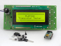
130544-1 Platino Transistor Tester
A Platino-based Transistor Tester to test transistors in a simple and portable way. Since it is tedious to read the markings on the transistor devices and to look up to its characteristics in datasheets, a handy transistor tester makes its way in such scenarioes.
Introduction
A simple Platino-based Transistor Tester is designed to test transistors in a simple and portable way. Since it is tedious to read the markings on the transistor devices and to look up to its characteristics in datasheets, a handy transistor tester makes its way in such senarioes.The Platino Transistor tester not only identifies the leads of the device but also the type and characteristics like Hfe of the device. The simplified Design of the Elektor’s Platino board makes it simpler to extend its capability to develop devices of complex functionality with a few enhancements.
The Platino Transistor tester is inspired by the "SC Analyser2005 Semiconductor Device Tester".
Specifications
- Power: 12V to 18V DC.
- Elektor Platino with ATmega32 microcontroller.
- 20 x 4 LCD Display.
- Elektor USB to Serial BoB module interface (110553) for debugging.
- Pluggable terminal block for easy mounting of transistor device to be tested.
Features
- Identifies transistor type, leads and characteristics.
- Indicates faulty or no transistor.
- Results can be viewed on LCD as well as in serial terminal.
- Easy and portable design.
Circuit description
The Platino Transistor tester has a hardware and software component; both interact strongly with each other to guarantee stability and accuracy of the device. The heart of the project is Elektor’s Platino Versatile AVR Board with an ATMega32 interfaced with Elektor’s FTDI USB to serial BOB module and a 20x4 LCD display along with rotary encoder with integrated push button for easy user interaction.
The ATmega32 microcontroller is used to read the voltages across the leads of the transistor in order to identify the leads of the device and to calculate the hfe. The Platino board is interfaced with the BOB module for the user to interact serially with the device
The add-on board placed on top of the Platino board is made up of three ICs 4052 for accurate switching between resistors for reading the voltages across the transistor leads connected to ADC pins of microcontroller. The rotary encoder connected to the platino board is used for interacting with the device through LCD.
Hardware
- Platino board with ATmega32 & 20x4 LCD
- Transistor tester Add-on Board.
Platino MCU board with LCD
The heart of the device is Elektor’s Platino board with 40-pin ATmega32 microcontroller used to read the voltages across the transistor leads identify the transistor and calculate the Hfe. It is clocked from its internal 8 MHz oscilllator.
See below for configuring the Platino board.
Transistor tester Add-on Board
The add-on board connected on top of the Platino board consists of two main sections
- The power section
- The switching section
The power section
The power section plays the main role in the add-on board. The 18V DC input voltage is applied to power section through connector K5. The input voltage is further send to IC1 MC7805 regulator which gives the necessary regulated voltage to the microcontroller and other components that operate on +5V supply.
The switching section
This section is made up of three 74HC4052 4:1 multiplexer IC’s each of which is connected to each lead of the transistor. Connected to the input of these multiplexer IC’s are the various resistor configurations required for measuring the various parameters of the transistor device connected
Software
The software for the project is written in BASCOM AVR for ATmega32 microcontroller running at 8 MHz. The Platino board is used for further development of the project. The software is made up of three main modules. They are as follows:
Display Section
The Display section displays the type of the transistor, the CBE pin numbers and the Hfe value of the transistor in common collector configuration.
Test Section
This section reads the voltage across each lead of the transistor. The multiplexer IC is used to switch the connections of the lead. The voltage across each lead of the transistor is read by connecting the lead to VCC via 5.6k resistor while the other two leads are connected to ground via 100 ohms. After reading the voltages across each lead, the base lead is identified by comparing the voltages of the leads, and using the fact that the voltage across the base pin is always different from the voltages across the other two pins. The identification of the type of transistor is done on the basis of the following table.
|
TYPE |
E |
B |
C |
Measured Voltage |
|
NPN |
GND |
GND |
VCC |
5V |
|
VCC |
GND |
GND |
5V |
|
|
GND |
VCC |
GND |
0.7V |
|
|
PNP |
GND |
GND |
VCC |
0.7V |
|
VCC |
GND |
GND |
0.7V |
|
|
GND |
VCC |
GND |
5V |
Hfe Calculation section
After the identification of the type and base lead of the transistor, the identification of the other two leads still remains unknown, this identification is done by assuming any one lead as collector lead and connecting the transistor in common collector configuration, calculate the Hfe.Next, we reverse the connections and calculate Hfe again. The greater Hfe value is considered as the correct one and hence the other leads of the transistor are identified.
Building the prototype
First build the Platino board with its LCD, rotary encoder with pushbutton, ATmega32 MCU and all other components, then ‘jumper’ it as shown below in Table 2
The add-on board that consists of the main circuitry for the transistor tester is connected to the Platino board via connectors K1, K2, K3 and K4. The Add-on board of Transistor tester is so designed to fix exactly to the back of Platino with the help of connectors.
Connect the Elektor’s USB to Serial BOB module (110553) if you wish to see the output on the serial terminal. The serial baud rate is set as 9600.
MCU Fuses
Low fuse: 0xA4 (BODEN, SUT0, CKSEL3, CKSEL1, CKSEL0)
High fuse: 0xCF (SPIEN, CKOPT)
Testing
Power up the device by connecting a 12V supply to connector K5. Connect the transistor to be checked to connector K6. When all the connections are done, press the push button of the rotary encoder or if the output is to be viewed on serial terminal then input ‘T’ from terminal.
IMPORTANT: in certain cases the program may hang waiting for the pushbutton to be pressed, showing "Press switch to test". This is because the program is also scanning the serial input for the character 'T'. However, if the serial input is left floating it may hang. To work around this problem either connect the serial port or connect PD0 to VCC, through a resistor (10k to 100k) or directly by placing a jumper on Platino connector K2 pins 3 (VCC) and 4 (RXD = PD0).
If this doesn't fix it, you can try the patched HEX file (Transistor_tester_LL_patched) available below. This HEX file simply skips the part where the serial port checks if it received the character 'T'. If you use this file you will not be able to start a test over the serial port.
Configuring Platino
| Pin designation | Function |
|---|---|
| PA0, PA1, PA2 | ADC inputs connected to DUT |
| PA7, PB3, PB4, PC0, PC1, PC7 | Multiplexer selectors |
| PA6, PB5, PC6 | Resistor pull-up/down |
| PB0, PB1, PB2 | Rotary encoder with integrated pushbutton |
| PC5 | LCD backlight control |
| Jumper | Position |
|---|---|
| JP3 | PC5 |
| JP4 | PB0 |
| JP5 | PB1 |
| JP6 | PB2 |
| JP7 | open |
| JP8 | '40' (PC6) |
| JP11 | PB7 |
| JP12 | PB6 |
| JP13 | PB5 |
| JP14 | PC7 |
| Platino v1.4 & higher | |
| JP15 | D |
| JP16 | D |
Component List Platino
Resistors, all 5%, 0.25W
R3 = 47 Ω
R4, R5, R6, R7, R10, R12 = 10 kΩ
R11 = 4.7 kΩ
P1 = 10 kΩ trimpot, horizontal
Capacitors
C5, C6 = 100 nF, 0.2” pitch
Inductor
L1 = 10 µH
Semiconductors
IC1 = ATmega32-16PU, programmed (Elektor Store # 130544-41)
T1 = BC547C (Platino 1.3) or 2N3904 (Platino 1.4, or BC547 mounted on LCD side)
D1 = 1N5817 (Platino 1.4 only)
Miscellaneous
S3A = pushbutton
K1 = 10-pin pinheader, 0.1” pitch, straight
K2, K6 = 6-pin pinheader, 0.1” pitch, straight
K3 = 6-way (2x3) pinheader, 0.1” pitch, straight
K5 = 8-way pinheader, 0.1” pitch, straight
K9 = 16-way pinheader socket, 0.1” pitch, straight
LCD1 = LCD, alphanumeric, 4x20 (Elektor Store # 120061-73)
DIP40 IC socket for IC1 (optional)
Platino PCB 150555-1
Discussion (2 comments)